

به نام خدا
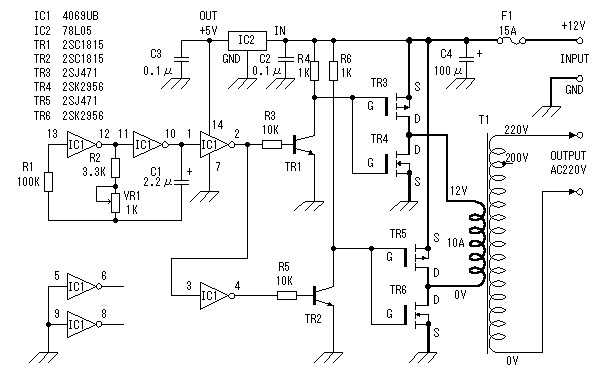
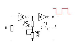
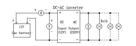
سلام امروز یه مدار واستون اماده کردم که تست شده وعالی کار می کنه.یه مدار یو پی اس که از دوقسمت یه قسمت اینورتر ویه قسمت منبع تغذیه که وقتی برق قطع شد باتری بک اپ رو خیلی سریع جای گزین می کنه.توان خروجی اینورترش حدود 40واته.میشه اینوترش رو حذف کرد و یو پی اس را به یک دستگاه 12ولتی متصلش کرد.خودم راحت تونستم یک لامپ کم مصرف 23واتی رو باهاش راه اندازی کنم.لامپ 100واتی رو هم روشن می کنه ولی نور کامل نیست(توان کمه)
به درد کار های کوچیک می خوره.
اینم مدارش:
[HIDE-THANKS] [/HIDE-THANKS]
مدار تست شده وبه درستی عمل می کنه می تونید با خیال راحت بسازیدش
امیدوارم مفید باشه براتون
سوالی بود در خدمتم
موفق باشید
سلام امروز یه مدار واستون اماده کردم که تست شده وعالی کار می کنه.یه مدار یو پی اس که از دوقسمت یه قسمت اینورتر ویه قسمت منبع تغذیه که وقتی برق قطع شد باتری بک اپ رو خیلی سریع جای گزین می کنه.توان خروجی اینورترش حدود 40واته.میشه اینوترش رو حذف کرد و یو پی اس را به یک دستگاه 12ولتی متصلش کرد.خودم راحت تونستم یک لامپ کم مصرف 23واتی رو باهاش راه اندازی کنم.لامپ 100واتی رو هم روشن می کنه ولی نور کامل نیست(توان کمه)
به درد کار های کوچیک می خوره.
اینم مدارش:
[HIDE-THANKS]
[/HIDE-THANKS]مدار تست شده وبه درستی عمل می کنه می تونید با خیال راحت بسازیدش
امیدوارم مفید باشه براتون
سوالی بود در خدمتم
موفق باشید
فایل های پیوست شده


دیدگاه