

سنسور نبض
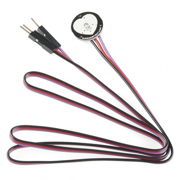
سنسور نبض آردوینو می تواند نبض را به سادگی اندازه گیری کند. پزشکان با استفاده از سنجش نبض سطح استرس ، آرامش ،آمادگی جسمانی ، وضعیت بهداشتی و ... تعیین می کنند. این اطلاعات به آسانی با استفاده از اندازه گیری لمسی بدست می آید. شما می توانید با استفاده از لمس کردن رگ های مچ دست یا گردن ضربان نبض خود را تعیین کنید. سنسور نبض در هر ناحیه از پوست (مانند انگشت یا نرمه گوش) تغییرات نامحسوس انبساط موی رگ های خونی برای سنجش ضربان قلب شما آشکار می کند. و آن پالس دیتا را به آردوینو شما برای پردازش می فرستد. اطلاعات مربوط به ضربان قلب می تواند برای طراحی یک روتین ورزش ، مطالعه روی فعالیت هایتان ، تعیین سطح اضطراب و یا پروژه های سرگرم کننده مفید باشد این سنسور ضربان بصری ساده قلب را تقویت کرده و نویزهای آن را حذف می کند تا خواندن آسان و مطمئن نبض را فراهم آورد.این سنسور با 3 یا 5 ولت و بوسیله آردوینو قابل راه اندازی است. مصرف جریان این سنسور در5V تنها 4mA است.
مثال
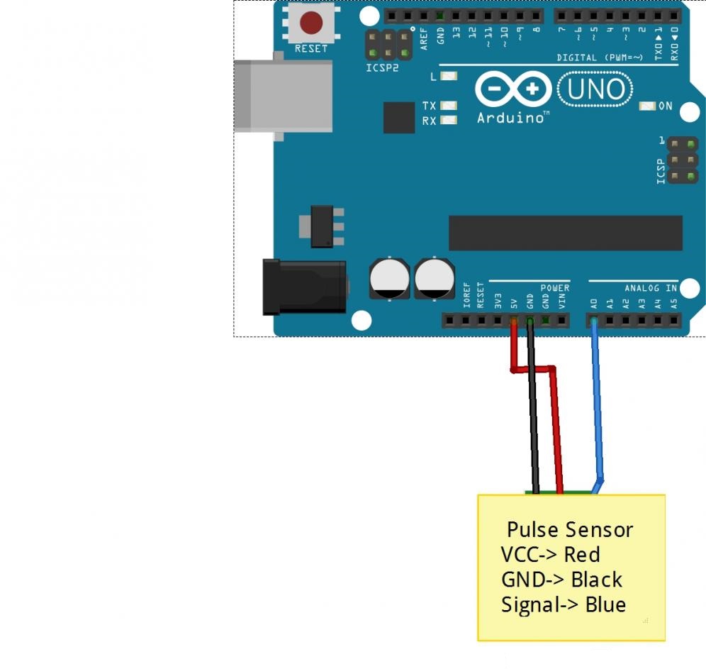
سنسور نبض در مثال زیر به همراه آردوینو امکان تعیین ضربان قلب را فراهم می کند LED پین 13 به همراه ضربان قلب چشمک می زند.
 لینک دانلود پروژه
سنسور نبض آردوینو می تواند نبض را به سادگی اندازه گیری کند. پزشکان با استفاده از سنجش نبض سطح استرس ، آرامش ،آمادگی جسمانی ، وضعیت بهداشتی و ... تعیین می کنند. این اطلاعات به آسانی با استفاده از اندازه گیری لمسی بدست می آید. شما می توانید با استفاده از لمس کردن رگ های مچ دست یا گردن ضربان نبض خود را تعیین کنید. سنسور نبض در هر ناحیه از پوست (مانند انگشت یا نرمه گوش) تغییرات نامحسوس انبساط موی رگ های خونی برای سنجش ضربان قلب شما آشکار می کند. و آن پالس دیتا را به آردوینو شما برای پردازش می فرستد. اطلاعات مربوط به ضربان قلب می تواند برای طراحی یک روتین ورزش ، مطالعه روی فعالیت هایتان ، تعیین سطح اضطراب و یا پروژه های سرگرم کننده مفید باشد این سنسور ضربان بصری ساده قلب را تقویت کرده و نویزهای آن را حذف می کند تا خواندن آسان و مطمئن نبض را فراهم آورد.این سنسور با 3 یا 5 ولت و بوسیله آردوینو قابل راه اندازی است. مصرف جریان این سنسور در5V تنها 4mA است.
مثال
سنسور نبض در مثال زیر به همراه آردوینو امکان تعیین ضربان قلب را فراهم می کند LED پین 13 به همراه ضربان قلب چشمک می زند.
کد HTML:
>>> Pulse Sensor purple wire goes to Analog Pin 0 <<<
Pulse Sensor sample aquisition and processing happens in the background via Timer 2 interrupt. 2mS sample rate.
PWM on pins 3 and 11 will not work when using this code, because we are using Timer 2!
The following variables are automatically updated:
Signal :    int that holds the analog signal data straight from the sensor. updated every 2mS.
IBI  :      int that holds the time interval between beats. 2mS resolution.
BPM  :      int that holds the heart rate value, derived every beat, from averaging previous 10 IBI values.
QS  :       boolean that is made true whenever Pulse is found and BPM is updated. User must reset.
Pulse :     boolean that is true when a heartbeat is sensed then false in time with pin13 LED going out.

This code is designed with output serial data to Processing sketch "PulseSensorAmped_Processing-xx"
The Processing sketch is a simple data visualizer.
All the work to find the heartbeat and determine the heartrate happens in the code below.
Pin 13 LED will blink with heartbeat.
If you want to use pin 13 for something else, adjust the interrupt handler
It will also fade an LED on pin fadePin with every beat. Put an LED and series resistor from fadePin to GND.
Check here for detailed code walkthrough:
http://pulsesensor.myshopify.com/pages/pulse-sensor-amped-arduino-v1dot1

Code Version 1.2 by Joel Murphy & Yury Gitman  Spring 2013
This update fixes the firstBeat and secondBeat flag usage so that realistic BPM is reported.

*/


//  VARIABLES
int pulsePin = 0;                 // Pulse Sensor purple wire connected to analog pin 0
int blinkPin = 13;                // pin to blink led at each beat
int fadePin = 5;                  // pin to do fancy classy fading blink at each beat
int fadeRate = 0;                 // used to fade LED on with PWM on fadePin


// these variables are volatile because they are used during the interrupt service routine!
volatile int BPM;                   // used to hold the pulse rate
volatile int Signal;                // holds the incoming raw data
volatile int IBI = 600;             // holds the time between beats, must be seeded!
volatile boolean Pulse = false;     // true when pulse wave is high, false when it's low
volatile boolean QS = false;        // becomes true when Arduoino finds a beat.


void setup(){
  pinMode(blinkPin,OUTPUT);         // pin that will blink to your heartbeat!
  pinMode(fadePin,OUTPUT);          // pin that will fade to your heartbeat!
  Serial.begin(115200);             // we agree to talk fast!
  interruptSetup();                 // sets up to read Pulse Sensor signal every 2mS
   // UN-COMMENT THE NEXT LINE IF YOU ARE POWERING The Pulse Sensor AT LOW VOLTAGE,
   // AND APPLY THAT VOLTAGE TO THE A-REF PIN
   //analogReference(EXTERNAL);
}


void loop(){
  sendDataToProcessing('S', Signal);     // send Processing the raw Pulse Sensor data
  if (QS == true){                       // Quantified Self flag is true when arduino finds a heartbeat
        fadeRate = 255;                  // Set 'fadeRate' Variable to 255 to fade LED with pulse
        sendDataToProcessing('B',BPM);   // send heart rate with a 'B' prefix
        sendDataToProcessing('Q',IBI);   // send time between beats with a 'Q' prefix
        QS = false;                      // reset the Quantified Self flag for next time
     }

  ledFadeToBeat();

  delay(20);                             //  take a break
}


void ledFadeToBeat(){
    fadeRate -= 15;                         //  set LED fade value
    fadeRate = constrain(fadeRate,0,255);   //  keep LED fade value from going into negative numbers!
    analogWrite(fadePin,fadeRate);          //  fade LED
  }


void sendDataToProcessing(char symbol, int data ){
    Serial.print(symbol);                // symbol prefix tells Processing what type of data is coming
    Serial.println(data);                // the data to send culminating in a carriage return
  }